
- BEARING CORP.OF CANADA LTD.
- Angular contact ball bearings Bearing units Cylindrical roller bearings

Home>Products>NTN Bearing>17 mm x 40 mm x 12 mm NTN 6203 Take Up Unit Bearings
NTN 6203 MODELS
Need a CAD or 3D Model?
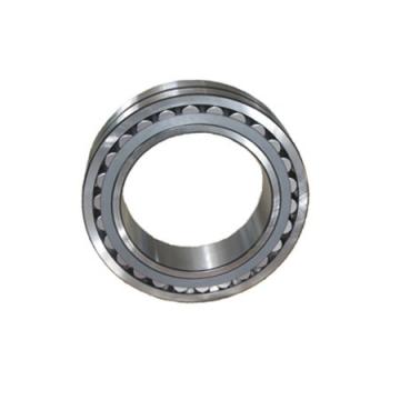
17 mm x 40 mm x 12 mm NTN 6203 Take Up Unit Bearings
category
NTN Bearing
NTN 6203 Bearing SPECIFICATIONS
17 mm x 40 mm x 12 mm NTN 6203 Take Up Unit Bearings Warehouse offers car parts and car accessories. We BEARING CORP.OF CANADA LTD. sell discount NTN Bearing online as 17 mm x 40 mm x 12 mm well as cheap machinery parts. 8930 lbf C90 - Dynamic Radial Rating (90 million revolutions)5
- NTN
6203
- 1.2188 in
- 0.03 in
- 8930 lbf
- 45289
- 0.1 in
- 15600 lbf
- 42600 lbf
- -0.32 in
-
 BEARING CORP.OF CANADA LTD.2020-07-10 09:46:19
Welcome to my shop! Glad to serve you! Please send your question!
BEARING CORP.OF CANADA LTD.2020-07-10 09:46:19
Welcome to my shop! Glad to serve you! Please send your question!
17 mm x 40 mm x 12 mm NTN 6203 Take Up Unit Bearings specification
- 1.2188 in
- 0.03 in
- 8930 lbf
- 45289
- 0.1 in
- 15600 lbf
- 42600 lbf
- -0.32 in
- Imperial
- 34500 lbf
- 17 mm x 40 mm x 12 mm
NTN 6203 17 mm x 40 mm x 12 mm NTN 6203 Take Up Unit Bearings Codes and sizes
| No. | Brand | d | R | J | C | S | L | B | H |
| 6204lu | NTN | - | - | - | - | - | - | - | - |
| 6203lhx3 | NTN | - | - | - | - | - | - | - | - |
| 6203lua | NTN | - | - | - | - | - | - | - | - |
| 6203lax30 | NTN | - | - | - | 20 mm | - | - | - | - |
| 6203lh | NTN | 6 mm | - | - | - | - | - | 9 mm | - |
| 6203lu | NTN | 20 mm | - | - | 18 mm | - | - | - | - |
| 6205lu | NTN | 20 mm | - | - | 12 mm | - | - | - | - |
| 6203 | NTN | - | - | - | - | - | - | - | - |
| 6203lh | NTN | - | - | - | - | - | - | - | - |
| sc8a37lhi | NTN | - | - | 127 mm | - | 17.5 mm | 167 mm | 42.9 mm | 95 mm |
| 6205 | NTN | 30,162 mm | 3,5 mm | - | 10,716 mm | - | - | 15,08 mm | - |
| NTN 6203lh Take Up Unit Bearings | Fatigue load limit - Pu:12.5 kN; EAN:7316577712523; Bearing number:NK 47/30; Fw:47 mm; Outer Diameter (mm):47; Weight / Kilogram:0.154; Inventory:0.0; Basic static load rating - C0:98 kN; Da max.:55 mm; Basic dynamic load rating - C:41.8 kN; |
| 25 mm x 52 mm x 15 mm NTN 6205 Take Up Unit Bearings | r:1 mm; T:14,684 mm; R:3,5 mm; B:15,08 mm; C:10,716 mm; Bearing number:08118/08237; Outer Diameter (mm):58,788; D:58,788 mm; d:30,162 mm; Width (mm):14,684; Size (mm):25 mm x 52 mm x 15 mm ; |
| NTN 6203lhx3 Take Up Unit Bearings | Dimension P:6.25 in; Dimension RVV:0.71 in; Pre Install Clearance Min:0.110 mm; C - Dynamic Load (Basic):86600 lb; Dimension J:4.88 in; Shaft Size Type:Imperial; Dimension G:1.88 in; Bearing Number:22219; Eng Internal Radial Clearance - Min:0.0043; Pre Install Clearance Max:0.140 mm; |
| NTN 6203lax30 Take Up Unit Bearings | Brand:KOYO; Bore Diameter (mm):18; Basic static load rating (C0):21.7 kN; Bearing number:NQ18/20; Weight:0.035 Kg; C:20 mm; r min.:0.3 mm; Size (mm):18x26x20; Basic dynamic load rating (C):14.1 kN; Fw:18 mm; |
| NTN 6203lua Take Up Unit Bearings | Dimension C:5.12 in; Grease Lubrication - T Seal:2000 rpm; Dimension A:4.41 in; Dimension M:2.60 in; C - Dynamic Load (Basic):79700 lb; Dimension D Min:11.42 in; Pre Install Clearance Max:0.0039 in; Dimension F:14.96 in; Dimension SA:4.02 in; Eng Internal Radial Clearance - Max:0.0039; |
| 17,000 mm x 40,000 mm x 12,000 mm NTN 6203lu Take Up Unit Bearings | d:20 mm; Brand:SKF; Width (mm):18; C:18 mm; Size (mm):17,000 mm x 40,000 mm x 12,000 mm ; Basic static load rating (C0):28 kN; Bore Diameter (mm):20; Outer Diameter (mm):52; Basic dynamic load rating (C):31 kN; Bearing number:2205E-2RS1KTN9+H305E; |
| NTN sc8a37lhi Take Up Unit Bearings | H2:140 mm; B:42.9 mm; H:95 mm; N1:21 mm; L:167 mm; S:17.5 mm; H1:19 mm; Bore Diameter (mm):35; J:127 mm; Brand:NACHI; |
| 20,000 mm x 47,000 mm x 14,000 mm NTN 6204lu Take Up Unit Bearings | Basic dynamic load rating (C):5,35 kN; Weight:0,0088 Kg; Bearing number:BHTM912-1; Fw:9 mm; Basic static load rating (C0):5,05 kN; Bore Diameter (mm):9; Width (mm):12; Brand:KOYO; D:16 mm; Outer Diameter (mm):16; Size (mm):20,000 mm x 47,000 mm x 14,000 mm ; |
| 25,000 mm x 52,000 mm x 15,000 mm NTN 6205lu Take Up Unit Bearings | Outer Diameter (mm):35; Bearing number:GE20N; Size (mm):25,000 mm x 52,000 mm x 15,000 mm ; Width (mm):16; d:20 mm; Brand:LS; Weight:0,064 Kg; C:12 mm; D:35 mm; dk:29 mm; |
| NTN 6203lh Take Up Unit Bearings | D:16 mm; r min.:0,3 mm; Bore Diameter (mm):6; h1:30 mm; Weight:0,01 Kg; d:6 mm; Brand:ISB; d5:13 r/min; B:9 mm; Bearing number:TSF 6 C; |
6203 Radial ball bearings : NTN-SNR, Industry Solutions
6203 Radial ball bearings on NTN-SNR catalog, Industry Solutions manufacturer for Single row deep groove ball bearings market
NTN - 6203 - Motion Industries
NTN 6203. Radial/Deep Groove Ball Bearing - Round Bore, 17 mm ID, 40 mm OD, 12 mm Width, Open, Internal Clearance: CN
NTN Bearing 6203 Single Row Deep Groove Radial Ball
Radial Ball Bearings. ... Single row radial ball bearings are the most widely used bearings and utilize an uninterrupted raceway, which makes these bearings suitable for radial loads, or a combination of thrust and radial loads. ... NTN is one of the three largest bearing companies in the
NTN Radial Ball Bearing, Double Sealed, 17mm Bore Dia
Looking for NTN Radial Ball Bearing, Double Sealed, 17mm Bore Dia., 40mm Outside ... Pressed Steel; Lubrication SRI#2 Grease; Industry Number 6203LLBC3
NTN Bearing 6203LU Single Row Deep Groove Radial Ball
NTN Bearing 6203LU Single Row Deep Groove Radial Ball Bearing, Contact, Normal Clearance, Steel Cage, 17 mm Bore ID, 40 mm OD, 12 mm Width, Single
Welcome to NTN Bearing
NTN is one of the world's leading manufacturers of bearing products to OEMs, distributors, and end users
BALL AND ROLLER BEARINGS - NTN Bearing
al centers around the globe, NTN Bearing Corporation is in an enviable ...... 6203 .6693. 1.5748 .4724 .024 .020. 2,160. 1,030 .143. 17. 40. 12 .6 .5. 6203/12.7
6203 NTN Single Row Ball Bearing for sale online | eBay
Find many great new & used options and get the best deals for 6203 NTN Single Row Ball Bearing at the best online prices at eBay! Free shipping for many
NTN - 6203/15.875 - Motion Industries
Buy NTN Radial & Deep Groove Ball Bearings 6203/15.875 direct from Motion Industries. Your proven service leader with reliable delivery since 1972
17 mm x 40 mm x 12 mm NTN 6203 Take Up Unit Bearings Video
NTN 6203 INTERCHANGE
NTN Bearing Part series 6203 is a potential replacement for these common bearing part numbers:
6203
6203
6203
6203
6203
6203
6203
6203
Contact Us
- BEARING CORP.OF CANADA LTD.
- Address4973 Levy Street, St-Laurent, Quebec, H4R 2N9, Canada
- Phone(Working Time)333-5623
- Fax
NTN 6203 Technical Articles
| BMT BEARING PRICE LIST |
| ZWZ BEARING PRICE LIST 2021 |
| KBC BEARING PRICE LIST |
NTN Bearing CATEGORIES
- Angular contact ball bearings
- Bearing units
- Cylindrical roller bearings
- Deep groove ball bearings
- Needle roller bearings
- Plain bearings
- Self aligning ball bearings
- Spherical roller bearings
- Tapered roller bearings
- Thrust ball bearings
- Thrust roller bearings
- Wheel bearings
- NTN Bearing
- timken lm29749 Bearing
- natr25 Bearing
- timken 37431a Bearing
- natr12 Bearing
- Large Slewing Bearings
- Slewing Ring Bearings
- Kaydon Slewing Bearing
- Bearing Slewing Ring
- Super Precision Bearings
- Super Precision Angular Contact Bearings
- Super Precision Bearing
- Slewing Ring
- Angular Contact Thrust Ball Bearings
- Four-Row Tapered Roller Bearing
- Thrust Spherical Roller Bearing
- Needle Aircraft Roller Bearings
- Double Row Tapered Thrust Roller Bearings
- Railway Rolling Spherical Roller Bearings
- Ribbed Drive Belts
- Gates Powergrip Timing Belt
- K060966 Belts
- Poly Rib Belts
- K060815 Belts
 NTN 6203lhx3 Take Up Unit Bearings
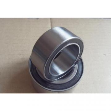 NTN 6203lua Take Up Unit Bearings
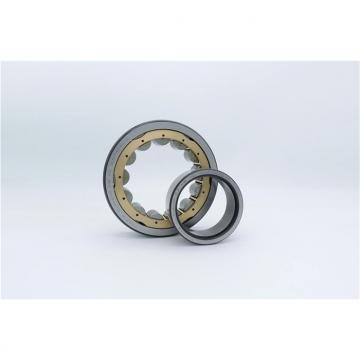 20,000 mm x 47,000 mm x 14,000 mm NTN 6204lu Take Up Unit Bearings
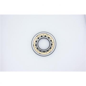 NTN sc8a37lhi Take Up Unit Bearings
 25 mm x 52 mm x 15 mm NTN 6205 Take Up Unit Bearings